Dividing Wall Column – Inside View
A closer look inside the DWC Prime column — internal zones, dividing wall design, and how multiple high-purity products are produced in a single shell.
DWC Prime · Inside View
Inside a DWC Prime dividing wall column
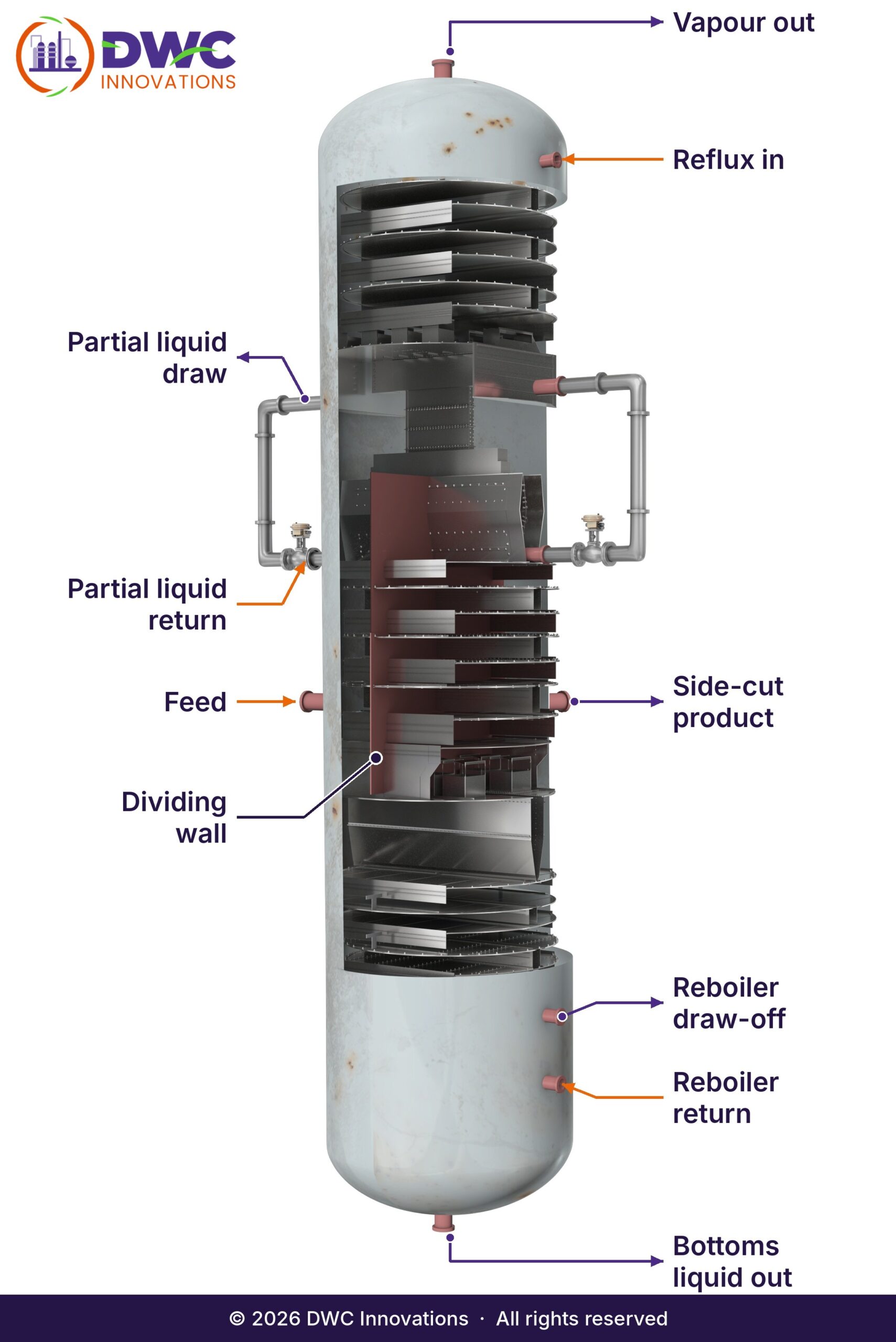
The DWC Prime design overcomes many of the limitations of conventional distillation sequences. Unlike traditional columns, Dividing Wall Columns (DWCs) incorporate one or more vertical partition walls within a single shell, creating distinct fractionation zones. These internal walls minimise the remixing of components that occurs in conventional arrangements, significantly improving separation efficiency. A DWC is, in effect, the mechanical and thermal integration of a Petlyuk column — the prefractionation and main fractionation regions are brought into a single shell.
Why it works
The penalty it removes is intrinsic to any conventional sequence. In the first column of a two-column sequence the intermediate-boiling component concentrates in the middle of the column; if it is not withdrawn there, it falls to the bottom and remixes with the heaviest component, and the downstream column then has to undo that remixing. The wall lets the intermediate component be taken where it is already concentrated, so the work is never wasted in the first place.
Column anatomy
DWC column design: four primary sections
A typical middle-wall DWC Prime column is built from four primary sections.
Top Common Section
The internal configuration resembles a conventional distillation column. Here the lightest components are separated from the intermediate-boiling components.
Prefractionation Section
The feed enters this zone, where the initial separation between light and heavy key components takes place — preparing the feed for enhanced downstream fractionation.
Main Section
The intermediate-boiling components are concentrated here. A rectifying section on the opposite side of the dividing wall enables withdrawal of a high-purity side-product stream.
Bottom Common Section
The heavy components are separated from the intermediate-boiling components to achieve the desired bottom-product purity.
Wall configuration
Where the wall sits — and what it changes
Not every dividing wall column has the wall in the middle. Where the partition sits determines how many products the column can make and which separations it suits.
| Configuration | Wall position | Typical outcome |
|---|---|---|
| Middle-wall DWC | Spans the centre of the column | The most widely used arrangement. Replaces two columns in sequence, or a single column with one or more side-cut streams. |
| Top-wall | Partition in the upper section only | Replaces a column integrated with a side stripper. Two separate condensing systems serve the two top products, so the overheads can be condensed at two different temperatures — which opens up overhead vapour heat integration. |
| Bottom-wall | Partition in the lower section only | Combines two columns that sit in an indirect sequence — where the top product of the first column feeds the second. Two separate reboilers allow the bottoms utility to be held at two different temperature levels. |
| Dual DWC Prime | Two walls in one shell | Four or more products from one shell; replaces three or more conventional columns. |
The trade-off
The middle wall gives the biggest saving, but it comes with a constraint worth stating plainly: it forces the cooling utility to the minimum temperature and the heating utility to the maximum. That is not always acceptable — a tight cold utility, or a fired heater already at its limit, can rule it out. A top- or bottom-wall arrangement buys the degree of freedom back by splitting the condensing or reboiling duty across two temperature levels.
The choice is driven by the feed, the product slate and — on a revamp — by what the existing shell will physically accept. Selecting the wrong configuration is the most expensive mistake available at concept stage, which is why we settle it during feasibility rather than during detailed design. See Dual DWC Prime →
How it works
The two splits that decide performance
Everything a dividing wall column does well or badly comes down to two numbers: how the liquid divides at the top of the wall, and how the vapour divides at the bottom.
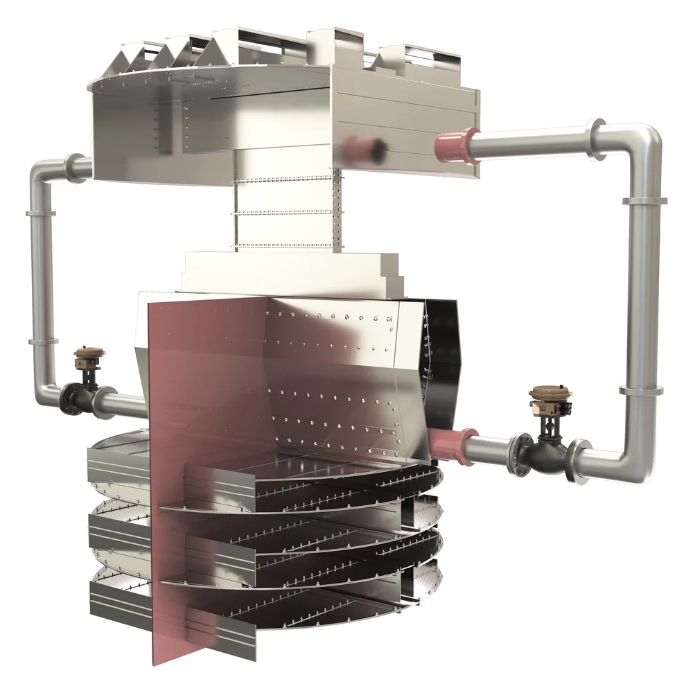 Liquid distributor above the dividing wall
Liquid split — the operator’s handle
A liquid distributor sits at the top of the dividing wall. Most of the split is handled internally, and a portion is drawn off and re-split in an adjustable ratio. That adjustable fraction is the column’s principal degree of freedom in operation: it shifts reflux between the prefractionation and main sides, letting the operator trade purity between the top and side products without touching reboiler duty.
Get the distributor wrong and no amount of reflux recovers the separation — liquid maldistribution across a partitioned cross-section is unforgiving, because each side is a narrower target than a full column.
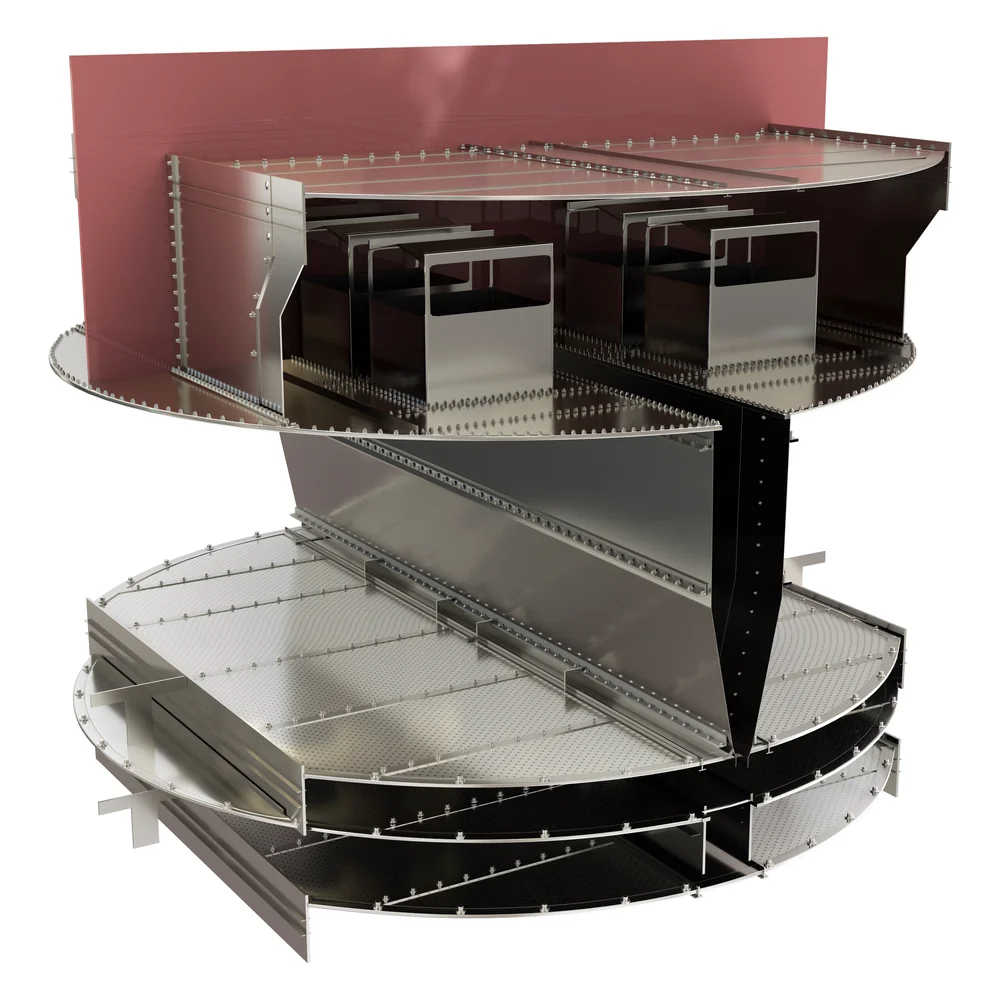 Base of the dividing wall, where vapour divides
Vapour split — set by hydraulics, not by valves
At the base of the partition, vapour rising from the bottom section divides and travels up either side. There is no control valve and no moving part. The split is set entirely by the relative pressure drop of the two sides — fixed at design stage by the internals, the wall position and the tray or packing selection on each side.
This is the part most often underestimated. The vapour split has to be right by design and verified hydraulically across the full turndown range, because it cannot be corrected in the field.
Fabrication
Building the wall
The partition looks like a simple plate. Three things decide whether it performs.
Welded or sectional
A welded wall is the simplest arrangement for a new column. For a revamp the wall can be built in sections and assembled inside the shell, which is what makes it possible to convert a column during a normal turnaround rather than cutting the shell open.
Heat transfer across the wall
The two sides operate at different temperatures, so heat crosses the partition. Whether that helps or hurts depends on the separation. It is accounted for in the design, and where it matters the wall is insulated.
Fabricated in-house
For our Indian projects the walls, liquid splitters and vapour distributors are fabricated in our own scope. That shortens delivery against imported internals and keeps fabrication inside the same quality loop as the design.
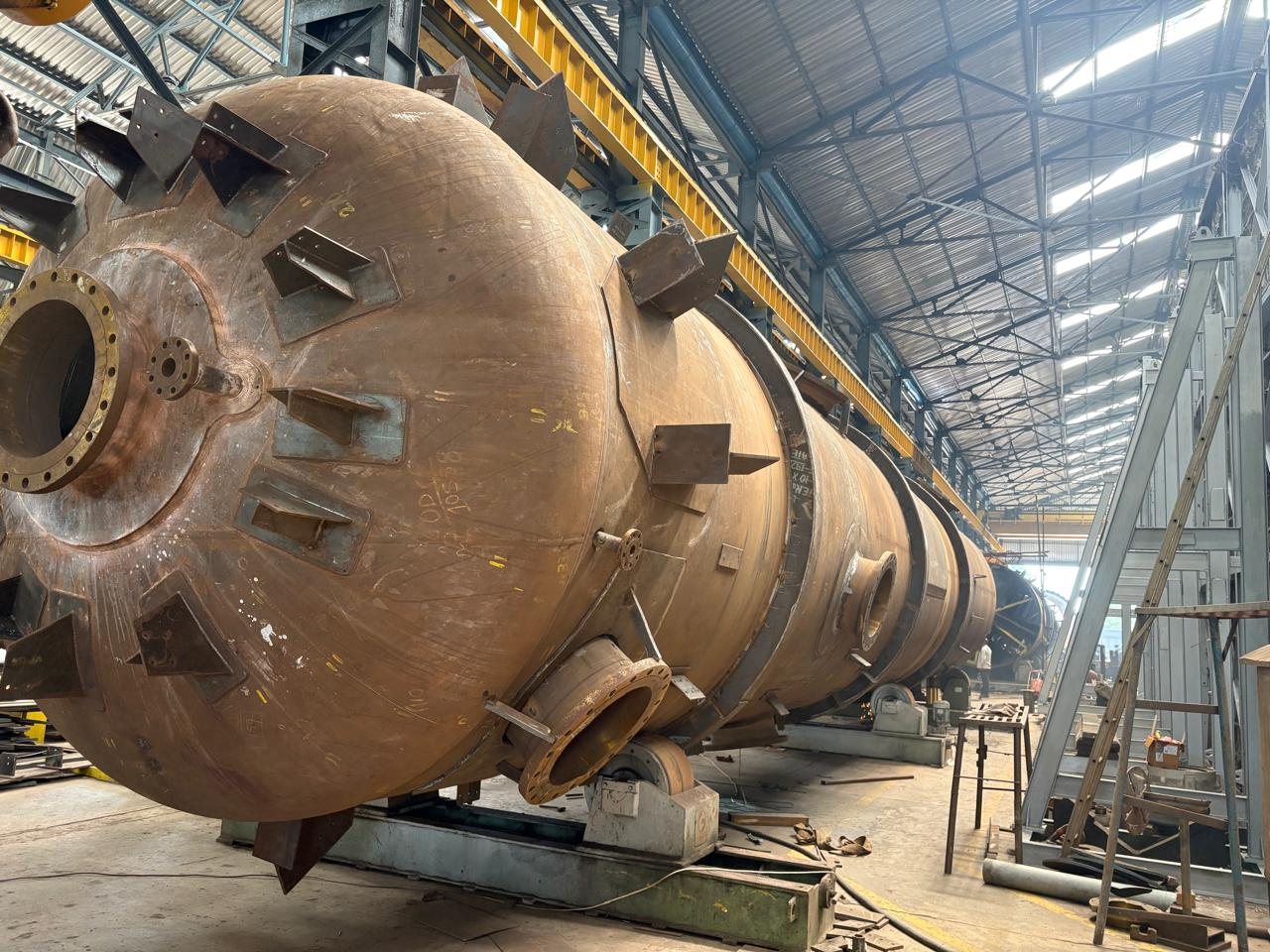
We build the walls we design
We fabricate and supply dividing wall columns, including dual-wall DWCs with two partitions in one shell. The column pictured is being built for a refinery in India. Wall position, flatness, the seal to the shell and the tray supports on both sides are checked against our process design before each section is closed.



Revamp
Fitting a dividing wall into an existing column
Most DWC projects are revamps, not grass-roots. Installing a dividing wall inside an existing shell follows a defined engineering sequence.
- Verify shell suitability. Diameter, tangent-to-tangent height, and nozzle locations determine whether the wall fits and where it can be positioned.
- Reconfigure internals. Existing trays or packing are replaced with hardware designed to achieve the required vapour split, not just the nominal stage count.
- Add required nozzles. Additional products require new draw-offs and typically a new rundown cooler.
- Assemble within the shell. Wall is erected and sealed; distributors installed and levelled.
- Commission against the model. The control scheme is proven before start-up, not learned during it.
Delivered this way, a naphtha splitter becomes a multi-cut Dual DWC inside its existing shell within a planned turnaround — as at MRPL. See the case studies →
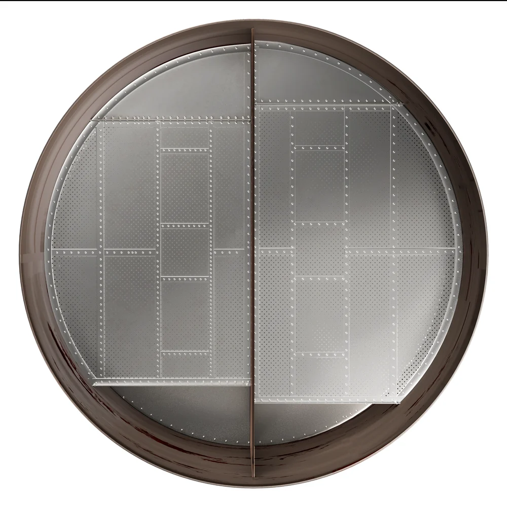 Plan view across the dividing wall — two independent fractionation zones in one shell
Internals
Trays or packing?
Both are used, and the choice is separation-driven rather than preference-driven. Packing gives low pressure drop per stage and suits vacuum and low-ΔP services; trays handle fouling and wide turndown better. In a dividing wall column the decision carries an extra constraint a conventional column does not have: whatever is selected on each side of the wall must deliver the intended vapour split at every operating case.
Operating and controlling a DWC
A dividing wall column is not harder to run than the two columns it replaces — it is one column instead of two, with one reboiler and one condenser to manage. What changes is that the liquid split becomes an additional handle, and the temperature control point has to be chosen with the wall in mind. We prove the control scheme in dynamic simulation before start-up, covering feed composition swings, rate changes and the turndown case.
Five design pitfalls worth avoiding
- Sizing for the stage count and letting the vapour split fall where it may.
- Treating the liquid distributor as a commodity item.
- Ignoring heat transfer across the wall in close-boiling separations.
- Fixing the wall position before the turndown case has been checked.
- Designing the column and the control scheme as separate exercises.
Why DWC Innovations
Designed, simulated and built by one team
Every wall position, split and control scheme on this page is set by our own process simulation and modelling, checked against plant operating data and carried through to fabrication by the same engineers. It is the approach behind more than 25 dividing wall column installations, including five commercial dual DWCs.
What is actually inside a dividing wall column?
How is the vapour split controlled?
How is the liquid split controlled?
Does the dividing wall need to be insulated?
Can a dividing wall be installed in an existing column?
Where should the wall sit?
Trays or packing inside a DWC?
Is a DWC harder to operate?
What limits how many products one column can make?
Want to see how DWC Prime performs inside your process?
Talk to our engineers about the internal design of DWC Prime for your application.